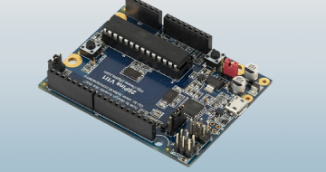
Learn to Design Your Own Boards by Udemy
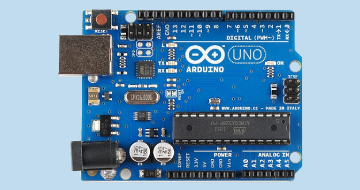
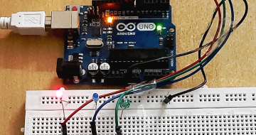
Design a board in 15 hours. Step-by-Step tutorial based on Arduino project (Altium)
Course Highlights
- After this course, you will design your own Arduino like board.
Skills you will learn!
Curriculum
79 Topics
Introduction
What you will learn during this course
Download Arduino schematic and start a new project
Prepare to create ATMEGA328P component
Create ATMEGA328P - Schematic symbol
Create ATMEGA328P - Footprint
Prepare to create ATMEGA16U2 component
Create ATMEGA16U2 - Schematic symbol
Create ATMEGA16U2 - Footprint
How to update an existing component
Create 10 pin female header
Create 8 pin female header
Create 6 pin female header
Connect 10 8 6 pin headers
Create 100nF capacitor
About connecting power pins of microcontroller
Create 10uF capacitor
Create Ferrite Bead
Draw power connections
Create 1M resistor
Create 16MHz Crystal
Create 18pF capacitor
Draw crystal circuit
Connect power header
Draw crystal connection and power for 16U2
Create ICSP header
Connect ICSP header
Placing net names
Using schematic filter and schematic inspector
Connecting rest of the IO connector signals
Create 22 Ohm resistor
About connecting CLOCK RX and TX
Create 1k Ohm resistor
Connect UART signals
Connecting ICSP1 header
Creating 2x2 male header
Connect 16U2 IO header
About RESET circuit
Creating BUTTON
Create 10k resistor
Creating DIODE
Create AND gate
Connecting RESET circuit
Draw rest of RESET connections
Creating 1x3 male header
Connecting JP1 jumper and 16U2 RESET circuit
Create 1x4 male header
Connecting JP3 jumper
Create Orange LED
Calculating LED resistor
Create 560 Ohm resistor
Connecting LEDs to indicate communication
Create and connect Green Power LED
Connecting User LED
Create +3.3V LDO regulator
Connect +3.3V LDO regulator
About power selection circuit
Create 0R resistor
Draw power selection circuit about unfitted components
Name some 16U2 nets and about pull up resistors
Create 100k resistor
Connecting 16U2 signals GND pins about UCAP
Create 1uF capacitor
Draw UCAP connection and name power & crystal nets
About USB connector + Creating USB connector schematic symbol
Creating USB connector footprint
Connecting USB - Part 1
Create Varistor
Connecting USB - Part 2
Creating 100uF capacitor
Create 2.2uH inductor
Connecting USB - Part 3
Add and connect User Button
Create and connect PADs
Create and add fiducials
Create and add mounting holes
Create and add DIP socket
Create and add LINK (jumper)
About PCB and Firmware component
6 Topics
Annotating checking and browsing schematics
Adding notes into schematic
Finishing schematic: About Pages Title Block and Parameters
About components and BOM (Bill of Material)
Update Altium Designer settings
Importing Schematic into PCB
12 Topics
Change board shape place mounting holes and main connectors
How to start placement place 328P MCU and DIP socket
Change Altium settings hide designators setup grid lock down components
About placement
Placement around 328P MCU
Placement around 16U2 MCU
Place components around USB connector
Placing headers jumpers and LDO regulator
Placing buttons 16U2 reset LEDs
Placing remaining components
3D view of finished placement
About paper model
20 Topics
Preparing for layout
Routing long connections
Routing short connections
Routing power nets
Routing ground net
Checking if everything is connected
Current status and about layout procedure for more complex boards
Importing schematic changes into PCB
Drawing power planes (polygons)
Drawing ground planes
More polygons improving power tracks and power planes
Improving layout Part 1
Improving layout Part 2
Improving layout Part 3
Improving silkscreen layer
Adding gold company logo
Adding assembly drawing layer
Creating mechanical drawing layer
Adding manufacturing notes layer
Finishing PCB
14 Topics
Create board variants
Start procedure of releasing your board documentation
Generate and check gerber files
Generating NC drill outputs and drawings
About stackup document
Generate mechanical drawing
Generate assembly drawing
Generate top view drawing
Generate BOMs
Generate pick and place file
About stencils
Generate 3D PDF and STEP file
Generate PDF schematic
Back up the project and what next ...
5 Topics
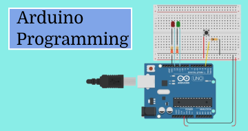
How to start with software development
Programming 16U2 MCU
Programming 328P MCU
Reprogram 16U2 MCU
Testing your board
1 Topic
Thank you very much for signing up for this course
Learn to Design Your Own Boards
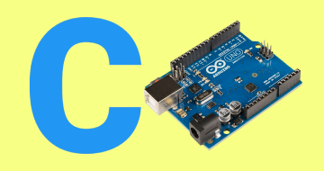
Related Arduino Courses


Thank You!
Your review has been submitted successfully.